

By Pratibha Sharma, Ph.D., Saya Han and Peter Chung, Violumas
Ultraviolet light is a known disinfectant, which reduces microbial load by denaturing pathogenic DNA. Wavelengths in the deep UV range, from 100 nm to 290 nm, with commercial devices available in the 200 nm to 280 nm range are the most suitable for microbial load reduction. While mercury lamps are commonly utilized in the disinfection market, the need for flexibility in form factors, no warm-up times and low maintenance has given way to commercial product development with ultraviolet light emitting diodes (UV LEDs). 1 UV LEDs have gained tremendous popularity over the past five years with applications ranging from curing and 3D printing to disinfection and horticulture. However, as a newer technology in the disinfection industry, there are several unknowns related to the design, simulation, characterization and development of UV LED based systems which need to be understood for optimal product development.
In this article, we walk through the process of designing a surface disinfection product using UV LEDs, beginning with user-defined application parameters and delving deeper into engineering design parameters. While bill-of-materials and product development costs may become significant factors for design choices, the focus of the article is on the technical aspects of device development.
Gathering User Requirements
The first step towards the development of any product is gathering user requirements, which should be clear, consistent, measurable and specific. In the case of a surface disinfection product, the application specific parameters must include the following:
Target disinfection object/surface
Looking at user targets, the specifications for disinfection devices can vary depending on where and how the device is going to be used – whether it is a healthcare facility, a food processing facility or a household setting. Depending on the application and the use case the microbial reduction targets and target pathogens may differ.
Target pathogen(s)
There may be many cases where a single pathogen is of interest. However, in most scenarios the target would be to eliminate multiple pathogens from the surface. This list should be well-established and researched before the device development commences.
Target microbial load reduction
Once the target pathogen is identified, the microbial load reduction targets should be determined based on facility requirements or application needs. For example, a food processing facility may require the reduction of Salmonella by 99.99% as compared to an airport mobile phone disinfection machine, which may have a 99.9% disinfection requirement.
Maximum exposure time
This parameter defines the maximum ON time of the device for one disinfection cycle. This parameter is directly determined based on product use cases. While the irradiance requirement may decrease significantly if the exposure time is increased, product users may not find it convenient for use if the exposure time is excessively long. For example, the maximum exposure time may be set to a few minutes for a mobile phone disinfection unit and not several hours, as it is for applications such as room disinfection.
Product form factor
The limitations on device form factor may have a great bearing on the engineering design of the device. If the device needs to fit within certain mechanical constraints, the number of LED sources, thermal management solution and electronics need to be chosen with consideration of the overall dimensions. The weight of the device may also be important, especially in handheld applications.
Process Map
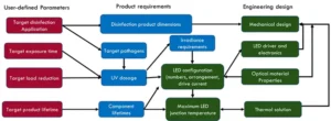
The device development process map (Figure 1) provides a snapshot of the interconnected components which need to be developed holistically to achieve user targets. UV intensity requirements derived from user-targets directly impact the electrical parameters and in turn the UV LED drive current. The UV LED optical output also is influenced by the junction temperature of the LEDs and therefore knowledge of LED drive current, corresponding junction temperatures and LED lifetimes is essential. Choice of thermal management solutions play a role in impacting both the electro-optical as well as the mechanical design of the device. Increasing thermal budgets would imply higher costs and potentially bulkier devices which may not be suitable, depending on the application. Parameters such as material properties, and device dimensions based on targeted disinfection objects need to be considered as well. Considering these factors, optimal device design becomes a complex task.
Engineering Design Parameters
Wavelength selection
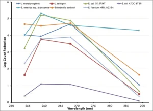
UV LEDs are commercially available in many different peak wavelengths. To select the most optimal wavelength, the microbial action spectrum must be examined. Figure 2 shows the action spectrum for food pathogens. 2
Most pathogens show a log reduction peak between 256 nm and 270 nm. Along with the action spectrum, it is also important to take note of the wall-plug efficiency of UV LEDs available at that wavelength. While the 265 nm peak wavelength may allow for better disinfection efficacy for many microbes, the 275 nm LED may have a higher electrical efficiency with a marginally lower microbial efficacy and so may be a better choice for product development.
UV Dosage
Once a suitable peak wavelength is identified for the target microbes, the next step is to determine dosage. Some microbes are more UV resistant than the others and hence require a higher dosage. Many published studies provide microbe-dependent and wavelength dependent dosage data. A comprehensive list of studies has been recently published by Masjoudi et al. 3
UV dosage defines the irradiance requirements within a target area: Irradiance (mW/ cm2) = UV Dose (mJ/cm2) / Exposure Time (s)
The irradiance requirement becomes the starting point for the optical designer to present a suitable solution.
Optical design
Optical design in tandem with thermal management plays the most important role in device development. Optical designers have many choices to make when it comes to designing sources and modules using UV LEDs. Here are some of the important parameters to be considered:
-
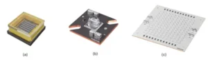
Figure 3: Examples of (a) an SMD product, (b) a COB product and (c) a custom UV LED array. UV LED Packages: UV LEDs are available in many different form factors. The flexibility and variety in chip sizes and packages provides many design choices to the optical designer. Commercial availability of packages may become a restrictive factor, so different varieties of products must be researched, including surface mount devices (SMD), standard chip-on-board (COB) products, multiunit LED modules, and custom designed arrays (Figure 3). 4
- LED output: The optical output of an LED is directly dependent on the drive current and junction temperature. Increase in junction temperatures can lead to a much-reduced optical output. While many manufacturers provide optical output (radiant flux) values at certain drive currents and junction temperatures, product developers should inquire about flux values at anticipated junction temperatures for their specific application. In addition, to maintain the irradiance at the surface, it may be essential to overdesign in terms of the LED output – applying dimming at the start of life and adaptively controlling the drive current to obtain target irradiance as the LED ages.
-
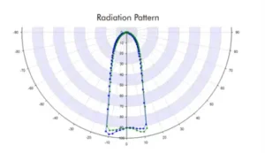
Figure 4: Sample radiation pattern of a UV LED with a 30° beam angle. 5 LED optics: Optical components such as lenses and reflectors can help in enhancing the target irradiance or uniformity. Fused silica and quartz materials are the materials of choice for their high UV transmission property. Commercially available UV LEDs come in many different beam angles and form factors. Optical beam angle, measured in degrees, refers to the angle at which the light intensity drops to 50% of the peak value. This information typically is presented in polar plots of radiation patterns provided in product datasheets (Figure 4).
-
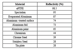
Table 1: Reflectivity of commonly used reflective materials (data obtained from Reference 6). Material reflectivity: Depending on the device’s design, there may be a need to use reflective materials in the device’s interior to maximize the effectiveness of UV LEDs. Table 1 shows a list of popular materials along with their reflectivity which may be used in the development of UV LED devices. 6
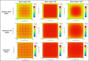
Optical simulations are a valuable tool to evaluate device, lens and material properties without any developmental costs. Obtained using optical simulations, Figure 5 shows the impact of lens angles and material reflectivity within a 20 cm x 20 cm disinfection box in an 18 cm x 18 cm target area.
In addition, it is important to consider irradiance distribution on the entire object, with regards to shadowing for a complex 3D structure. In such cases, UV LEDs’ locations and array designs can be custom designed to reach those areas. The benefit of using UV LEDs clearly is seen when it comes to custom designs.
LED driver selection
LEDs are driven by direct current (DC) and cannot be powered directly from standard AC wall power. LED drivers convert the AC wall power to a DC signal. The selection of an optimal power supply is vital to obtain the desired optical output, suitable lifetimes, and the desired reliability from the LEDs. 7 The forward voltage of the LED must be matched with the output voltage range of the driver. Typically, LEDs are driven using constant-current power supplies, so the maximum output current of the driver must be matched with the LED drive current. Using an incorrect power supply can not only damage your LED product but can also be a source of dangerous electrical hazards. Hence, the power supply should be chosen with utmost caution, keeping in mind the specific characteristics which closely match the requirements of the application and the LEDs being used. LED may be driven using a constant-current mode or using pulse width modulation. In many cases, dimming the LED may be needed to match with a commercially available power supply. Knowledge of the current-voltage LED data is necessary to choose the correct driver.
Thermal management solution
Heat affects many aspects of the LED including its lifetime and light output. Increase in junction temperatures can lead to temporary or permanent degradation in the different layers of the LED and hence affect reliability and lifetime. 8 In addition, UV LED light output decreases with an increase in temperature, since the quantum efficiency decreases at higher temperature that contributes to more nonradiative recombination events in LEDs.
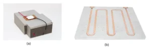
Therefore, design of an optimal thermal solution should be a mandatory part of the device development process. Heat management may be incorporated at the package level by using low resistance thermal paths or by using metal core PCBs. At the system level, both active and passive cooling methods may be deployed. Heat sinks with high thermal conductivity and large surface areas can help with heat extraction. Well-spaced metal fins can be designed in various shapes for maximizing surface area and improving fluid flow. In many cases the fluid is air, however high-heat transfer fluids including water may be used. In addition, surface textures and finishes such as powder coatings, paints and anodized coatings may provide better thermal dissipation than untreated surfaces. Active cooling is enabled using fans for forced air-convection. This can help reduce the size and cost of the heatsink (Figure 6).
Thermal modeling can be a powerful tool to obtain quick results with various thermal solution combinations.
Mechanical and industrial design
- Form factor: The initial guidelines for the form factor would be determined from the user requirements and may limit the mechanical designer to design the housing for the disinfection device. Industrial design may also be important keeping in mind user-acceptance criterion.
- Ergonomics and weight: These factors may have an important role to play specifically if the device is a handheld device.
Mechanical designers must work in tandem with optical and thermal designers for optimal product design. CAD modeling allows for many design iterations, without high costs of development and is a popular tool in the development stages.
Other features should be considered during the design phase.
Modularity
Having a modular design can be beneficial in many ways, including:
- enabling rapid end-product development and evolution,
- minimizing risk in new product development,
- simplifying prototyping,
- enabling quick changes in product design and
- simplifying product replacement/maintenance and lowering maintenance costs.
Safety
Exposure metrics for the wavelength of interest must be considered. UV-C exposure within 250 to 280 nm is harmful for humans and so dosages must be carefully examined while avoiding any leakage.
Conclusion
UV LEDs are being employed for many disinfection applications. However, the product design process must be understood in depth before product development is commenced. Efficient design requires meticulous evaluation of components and a clear vision on the device’s usage. The process while appearing to be straightforward becomes complex as the dependence of various engineering components is realized. Hence, the design, driven by user requirements, must be done holistically to account for optical, electrical, mechanical and thermal components.
Pratibha Sharma, Ph.D., is director of Applications Research and Development for Violumas. Saya Han is sales director, and Peter Chung is in marketing. For more information, visit www.violumas.com.
References
- Muramoto Y, Kimura M, Nouda S (2014) Development and future of ultraviolet light-emitting diodes: UV-LED will replace the UV lamp. Semiconductor Science and Technology 29:084004. Available at https://iopscience.iop.org/article/10.1088/0268- 1242/29/8/084004
- Green A, Master’s thesis: https://dam-oclc.bac-lac.gc.ca/download?is_thesis=1&oclc_number=1252218502&id=a74929bb-b8a4-4d42-b5e2-54dafed88ee6&fileName=Green_Andrew_201812_MSc.pdf
- Masjoudi M, Mohseni M, Bolton JR (2021) Sensitivity of bacteria, protozoa, viruses, and other microorganisms to ultraviolet radiation. Journal of Research of the National Institute of Standards and Technology 126:126021. https://doi.org/10.6028/jres.126.021
- Violumas (2024) UV-LED Datasheets (Violumas, Fremont, CA). Available at https://www.violumas.com/.
- Violumas (2024) UV-LED Datasheet Sample (Violumas, Fremont, CA). Available at https://www.violumas.com/wp-content/uploads/2021/08/VC1X1C48L3-265-Rev080621.pdf
- Kowalski W, Doctoral thesis: https://etda.libraries.psu.edu/files/final_submissions/6584
- Wang Y, Alonso J, & Ruan, X. (2017). A Review of LED Drivers and Related Technologies. IEEE Transactions on Industrial Electronics. PP. 1-1. 10.1109/TIE.2017.2677335.
- Sharma P, Chen P, Han S, Chung P, Chen J, Tseng J, Han C (2021) Design Considerations for a Surface Disinfection Device Using Ultraviolet-C Light-Emitting Diodes. J Res Natl Inst Stan 126:126045. https://doi.org/10.6028/jres.126.045.