

Felix Becker, Ph.D. , system and application manager, ZED Ziegler Electronic Devices GmbH
Thomas Rathgen, head of technical department, ZED
Rolf Ziegler, Ph.D., technical director, ZED
Karin Ziegler, CEO, ZED
Water treatment with UV low-pressure mercury vapor lamps is an established method to reduce pathogens in municipal drinking water.1,2 The performance of UV disinfection plants is monitored by plant radiometers.
To guarantee constant quality, plant radiometers are annually checked and calibrated using specialized reference radiometers according to the Austrian Standard M 5873. The 2020 amendment3 of this standard replaces the almost 20-years-valid previous standard4 which, thanks to its concrete application-oriented specifications, had great influence far beyond Austria’s borders. In the new third part, ÖNORM M 5873-3:2020-01,3 reference radiometers (RRM) are separately addressed. Requirements and test conditions are updated and detailed. Furthermore, recent radiometer designs with an enhanced functionality are considered.
Application
A reference radiometer according to the Austrian Standard M 5873 is a mobile UV-C radiometer with stringent requirements concerning measuring accuracy, stability against environmental conditions, calibration and documentation.1,2 The purpose of RRMs is the annual checking of plant radiometers and control measurements in UV plants with UV low-pressure lamps for disinfection of drinking water.
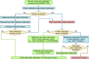
Figure 1 illustrates the use of RRMs with and without in-field calibration feature. In a running disinfection plant, the UV sensors are checked. Therefore, the UV-C irradiance is measured with plant radiometer and RRM directly, one after the other. If the value of irradiance differs or the validity of the calibration is expired, the plant sensor will be exchanged or, in the worst case, the UV plant needs to be shut down.
To avoid this, modern UV sensor solutions with digital interface can be calibrated in-field with a compatible RRM. The calibration measurements are directly carried out in the measuring window of the plant sensor in a running UV plant. First, a test measurement with the RRM is carried out. The measured value is cached in the flash memory of the RRM. Then, a compatible plant sensor with internal microcontroller and variable amplification is connected to the RRM. The calibration factors and the calibration date are stored in the protected memory of the plant sensor. The sensor is calibrated with validity of one year, according to the Austrian Standard M 5873. The UV plant needs no change.
Why the new Austrian Standard M 5873-3:2020-01?
Austrian standards, as well as German standards DIN, are recommendations. It is – in principle – free to what extent the M 5873 is used. Only in a few cases is the observance of Austrian standards mandated by laws or edicts, but they can be agreed in contracts. M 5873 defines requirements for design, operation and monitoring of disinfection systems with mercury vapor lamps for the treatment of drinking water. The application of the conditions specified in the standard will ensure the disinfection of drinking water complies with the requirements of the applicable food law regulations.
The previous regulation Austrian Standard M 5873:2001-033 was widely used beyond the borders of Austria and was recently replaced, after almost 20 years of validity, by the current edition Austrian Standard M 5873: 2020-01.3 The current issue originated from the cooperation of the Austrian committee 140 “Wasserqualität” and the working group of DVGW/DIN responsible for drinking water disinfection with UV devices in Germany. As a result, a harmonization of national requirements for testing the devices for water disinfecting by means of UV radiation has been achieved. Austrian Standard M 5873 and German Standard DIN 19294 are identical in terms of content.
The currently valid Austrian Standard M 5873: 2020-01 “Devices for the Disinfection of Water using Ultraviolet Radiation” includes three parts:
- Part 1: Requirements and testing of devices equipped with UV low-pressure lamps
- Part 2: Equipment with medium-pressure mercury vapor lamps
- Part 3: Requirements and testing of reference radiometers
In the novel third part, the requirements and test conditions of RRMs for devices with UV low-pressure lamps are updated and detailed. That a radiometer meets the requirements can be proven with:
- Self-declaration by the manufacturer “First Party”
- Supplier rating by the user “Second Party” or
- Certification by an independent body “Third Party”
It is common to have RRMs certified by independent bodies, because of the outstanding importance of RRMs for evaluating the performance of devices for disinfecting drinking water as well as for testing plant radiometers.
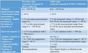
In Table 1, the requirements of RRMs for a certification according to the Austrian Standard M 5873: 2020-013 and the previous requirements4 are compared. It shows that the established specifications are mostly maintained, but the values for measurement range, display accuracy and direction sensitivity are slightly tightened, as it is shown in Figure 2. None of the established RRMs on the market1 should lose their certification status.
An RRM, according to the valid standard, should measure the value of UV-C irradiance of low-pressure lamps in the range from 0.01 W/m² up to minimal 250 W/m² with an uncertainty of 10% at the most. For values below 0.01 W/m², the RRM displays 0 W/m². If values are measured above the maximal range, the RRM clearly signals the overflow. In disinfection plants with UV low-pressure lamps, often values of irradiation are measured above the minimal range up to 250 W/m². To perform test measurements and an in-field calibration, as shown in Figure 1, an extended measurement range up to 500 W/m² brings a higher flexibility. The novel standard allows this range extension and defines the valid requirements.
The total measurement uncertainty u is calculated as the square root of the individual values of uncertainties: resolution and display accuracy u1, deviation of linearity u2, uncertainty of the spectral sensitivity u3, variability of angular response u4 and temperature sensitivity u5.
![]()
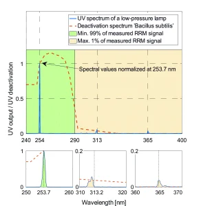
An RRM displays the measured values of irradiance with an accuracy u1 of 1% over the measurement range and a minimal resolution of 0.01 W/m² below a value of 1 W/m². The dependency is linear with allowed deviations u2 over the entire measurement range of maximum 5%. The UV spectrum of low-pressure lamps has, beside its dominant peak at 253.7 nm, further peaks above 300 nm, see Figure 3. Microbicidal effective radiation ranges from 240 up to 290 nm, as it is illustrated in Figure 3 by the deactivation curve of Bacillus subtilis WDCM 000034 normalized to a value of 100% at 253.7 nm. According to the standard, radiation above 290 nm may not contribute more than 1% to the measured value of the RRM.
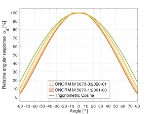
The spectral sensitivity u3 is tested using filters specified in the standard. The value u4 is defined by the difference between maximal and minimal angular sensitivity, see Figure 2. Temperature changes within the expected boundaries should have an influence u5 of maximal 0.1% to measurement signal. All values need to remain within the limits for at least one year.
The standard demands an annual calibration with traceability to a national metrological institute. The date of calibration and validity of calibration need to be labeled or shown on a digital display. The calibration factor must be protected from manipulation.
Design and functionality of a reference radiometer
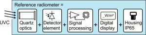
The functional units of an RRM are shown schematically in Figure 4. The input optics consists of a circular quartz glass window of Ø15 mm or another material (e.g., PTFE) that has optical and mechanical properties comparable to those of quartz glass. The input optics is scratch-resistant and fixed in a housing with standardized dimensions: Ø20 mm fitting h9 and a length of 59 mm ± 0.1 mm. Usually, the housing is made of stainless steel. UV sensitive detector elements are photodiodes or photocells. They produce a current proportional to the UV radiation in the range from picoampere to microampere. The photocurrent is amplified by electronic signal processing and converted into a digital value of irradiance. The value is shown on a digital display in the W/m² unit. To achieve the required accuracy – compare Table 1 – the measurement range is selected manually by the user or automatically by an integrated microcontroller. Since RRMs may be used under adverse industrial conditions, features such as protection class IP65, accumulator or battery operation and a well-readable display, illuminated if necessary, are required.
Practical realization
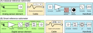
The available RRMs1 can be roughly classified by their electronic design and functionality into two groups: (A) classical RRMs with an analog UV sensor and (B) smart RRMs with a digital UV sensor, illustrated in Figure 5.
As the electronic signal processing of classical radiometers (A) is integrated in the handheld part, the sensor head has a simple electronic design. The UV-sensitive element is directly connected to the cable. An additional power supply of the sensor head is not necessary. The photocurrent flows through the cable and is amplified and converted in the handheld part of the radiometer. The radiometer is calibrated by adjusting the amplification factors in the handheld part of every measurement range individually. As UV detectors and electrical connectors differ slightly from each other due to manufacturing tolerances, the calibration of the handheld is only valid with the associated sensor element. The overall system needs to be calibrated annually. Components of classical RRMs cannot be exchanged separately without violating the regulations.
Smart RRMs (B) integrate all functional units for a standard-compliant UV reference measurement in the sensor unit. Signal amplification, conversion and measurement range selection are automatically realized with an integrated microcontroller. The signal is transmitted digitally, e.g., via RS485 to a handheld unit that displays the value of irradiance. The calibration data is stored in the protected memory of the microcontroller. As the digital sensor element is a calibrated radiometer itself, it is independent of the used handheld. This allows greater flexibility and availability of the system. The sensor element can be exchanged, and alternative display units – like PLC, laptop or IP65-handheld – can be applied.
Modern smart radiometers often have additional functions like graphical display, in-field calibration option, value forwarding or data logging on SD card. A smart RRM (B) is technologically more sophisticated compared to a classical RRM (A) and, therefore, requires an increased development effort by the manufacturer. The user benefits from the advantages.
Conclusions
RRMs are used to ensure the UV performance of disinfection plants with UV low-pressure lamps, especially in drinking water applications. The new Austrian Standard M 5873-3: 2020-01 defines requirements and test conditions for RRMs. The regulations are updated and detailed. Modern digital radiometer designs are considered. RRMs with an extended measurement range of 0.01 W/m² up to 500 W/m² and the in-field calibration feature can save time and money with full conformity, quality and accuracy.
Contact: Felix Becker, f.becker@z-e-d.com; Thomas Rathgen, t.rathgen@z-e-d.com; Rolf Ziegler, r.ziegler@z-e-d.com; Karin Zeigler, k.ziegler@z-e-d.com
References
- Schmalwieser, A. W. 15 Years experiences with standardized reference radiometers for controlling low-pressure UV disinfection plants for drinking water; Water Science & Technology – Water Supply. 2017, 17(4), S. 975-984.
- Sommer, R., Cabaj, A., Haider, T., Hirschmann, G. UV Drinking Water Disinfection –Requirements, Testing and Surveillance: Exemplified by the Austrian National Standards M 5873-1 and M 5873-2; IUVA News, 2004, 6(4), S. 27-35.
- Austrian Standard ÖNORM M 5873-3:2020-01, 2020, Devices for the disinfection of water using ultraviolet radiation – Part 3: Reference radiometers for devices equipped with UV low-pressure lamps -Requirements and testing; Austrian Standards Institute, Vienna, Austria.
- Austrian Standard ÖNORM M 5873-1:2001-03, 2001, Plants for disinfection of water using ultraviolet radiation – Requirements and Testing – Part 1: Low-pressure Mercury Lamp Plants; Austrian Standards Institute, Vienna, Austria.
- Cabaj, A., Sommer, R., Pribil, W., Haider, T. The spectral UV sensitivity of microorganisms used in biodosimetry; Water Science & Technology – Water Supply. 2002, 2(3), S. 175-181.