

Pablo Fredes, project manager, Hydraluvx UV Disinfection Technologies; Ulrich Raff, optics and semiconductors lab, Physics Department, University de Santiago de Chile; Ernesto Gramsch, optics and semiconductors lab, Physics Department, University de Santiago de Chile
In the solid state lighting industry, many research groups have shifted their focus toward the shorter wavelengths in the UV-C range, leading to potential applications of UV-C LEDs in air, water and surface disinfection processes, biophotonics research, biomedical and microbiological instrumentations, and many other applications. The complexity of a reliable UV-C LED performance depends upon optical efficiency, adequate lifetime and wavelength accuracy that concern all technological applications. While great advancements have been made in increasing the external quantum efficiency (EQE) of the LEDs, the performance of the devices continues to be very sensitive to the ambient temperature.
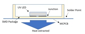
The first UV-C LEDs were primarily packaged in relatively expensive and thermally inefficient transistor outline-type housing.1 To improve the heat extraction from the junction, most of the UV-C LEDs are mounted in surface modules device packaging (SMD) commonly in 3.6 x 3.6 mm2 or 5 x 5 mm2 format for each LED.
The thermal dependence of the optical performance of UV LED has been studied by Kheyrandish et al. showing that higher solder point temperatures (TS) resulted in lower optical output power, shifts of the peak wavelength and an increase of the full width at half maximum (FWHM).2 Recent published results have shown that the lifetime decreases more with a current of 350 mA than with 100 mA.3 This means that with increasing LED current, the temperature increases; i.e., decreasing the relative optical output power.
Heat extraction from the AlGaN semiconductor structure is one of the key technical challenges to be considered.4, 5
Thermal management
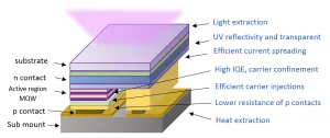
The relatively high resistance of the ohmic contacts, the p and n type cladding layers in the semiconductor structure, as well as poor thermal conductivity, lead to high operating voltages and consequently Joule heating in the device.4, 5 This produces self-heating that reduces the optimal radiative electron hole recombination in the multiple quantum well region of the semiconductor structure and stressing the crystal structure along the operation time.
Efficient thermal management becomes critical to ensure the high optical efficiency and lifetime. To resolve this challenge, the thermal conductivity of the package must be considered; therefore, the thermal resistance must be provided by the manufacturer. Metal core printed circuit boards (MCPCB) with high thermal conductivity are also recommended.
Another important parameter is the junction temperature. The manufacturer must indicate the maximum allowed value of the junction temperature in continuous wave operation.
The junction temperature TJ and solder point temperature TS are related with the rate of thermal conduction between junction and solder point and the thermal resistance RJ-S. It is possible to determine the junction temperature TJ related to the solder temperature TS, using the following relation including wall plug efficiency factor (WPE) that will be defined in the next section, where ILED and VLED are the electrical current and applied forward voltage, respectively.
TJ = TS + RJ-S(1–WPE)ILEDVLED (1)
This means that it is possible to determine the junction temperature to control it. The application of the efficient heat extraction technique will allow considerable reduction of junction temperature, producing greater light emission.6
Wall plug efficiency and junction temperature
The rate between electrical power consumption PLED and optical output power of the LED devices PLIGHT is called wall plug efficiency (WPE). As Kneissl has shown, the WPE is proportional to the EQE factor (ηEQE) and the rate between optical energy (hν) and electrical energy (eV) as is shown in the next equation.7
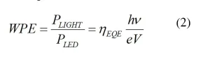
Where h is Planck’s constant, ν is the frequency of the UV photon, e is the elementary electric charge, V is the voltage and ηEQE the external quantum efficiency factor.
The external quantum efficiency (EQE) is defined as the ratio of the number of photons emitted from the LED per second to the number of carriers (electrons) injected into the device per second.
Electron-hole recombination and its dependence with temperature
According to semiconductors theory, the thermal excitation of electrons from the valence band into the conduction band results in the generation of electron-hole pairs. Thermal equilibrium requires that this generation process be accompanied by a simultaneous reverse process of deexcitation, called electron-hole recombination. It happens when an electron decays from the conduction band to fill a hole in the valence band. The energy released may take the form of emitted photon. This process is called radiative electron-hole recombination.
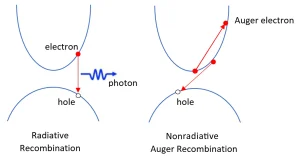
Nonradiative electron hole recombination can occur for a number of reasons, including kinetic energy transference, producing lattice vibrations (phonons creation) or another free electron (Auger process)8, as is shown in Figure 3.
The efficiency drop mechanisms in the light generation has been studied by Verzellesi.9 Then Iveland concluded that the Auger Recombination is the most relevant nonradiative process in the GaN-based LEDs.10 Different Auger processes are at play in GaN-based LEDs.
Direct (i.e., phonon-less) processes in bulk semiconductors exhibit an exponential dependence of the rate with temperature, which arises from a characteristic threshold energy implied by energy and momentum conservation.9
Thermoelectric cooler device to control the temperature performance
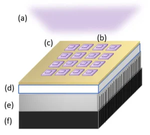
The main interest is promoting the radiative recombination in the semiconductor structure by the heat extraction. To face the challenge, the use of the thermoelectric cooler devices (TEC) – such as active heat extractor and temperature controller – is proposed. The TEC module is a specific semiconductor array that uses the Peltier effect to produce a temperature gradient between opposite sides when a voltage is applied, resulting in a cold side and hot side of the TEC. It is possible to mount the MCPCB with a single LED or array on the cold side of the TEC and put an aluminum heat dissipater and fan on the hot side of the TEC. The temperature can be reduced considerably – around 10°C – in the solder point.
The TEC device allows the use of PID controllers to act where ambient temperatures change. The most popular commercial TEC device is TEC1-12706, with 4 cm x 4 cm x 0.4 cm dimensions.
It is possible to apply a thermal control model for LED arrays. Thermal distribution between every LED package and the total area of the MCPCB must be considered. With thermal contact between the cold side of the TEC, the heat will be extracted from the LED arrays, promoting the macroscopic thermal conditions to produce more radiative electron hole recombination and improved optical performance.
Conclusions
Fusion of the UV-C LED and the TEC semiconductor devices onto the same chip can improve the optical performance from this unique chip while delivering the same benefits of the two separate semiconductor devices. Further research to fully explore these potential benefits is warranted.
Contact: pablo.fredes@usach.cl; ulrich.raff@usach.cl; ernest.gramsch@usach.cl
References
- O. Lawal, J. Cosman, and J. Pagan, “UV-C LED Devices and Systems: Current and Future State,” IUVA News, vol. 20, no. 1, pp. 22–28, 2018.
- A. Kheyrandish, M. Mohseni, and F. Taghipour, “Development of a method for the characterization and operation of UV-LED for water treatment,” Water Res., vol. 122, pp. 570–579, Oct. 2017.
- C. Pernot, “Improving Deep UV LED Performance,” in LED China Conference, 2016, pp. 1–33.
- M. Kneissl and J. Rass, III-Nitride Ultraviolet Emitters Technology and Applications, vol. 97, no. 2005. 2017.
- N. Lobo Ploch et al., “Effective thermal management in ultraviolet light-emitting diodes with micro-LED arrays,” IEEE Trans. Electron Devices, vol. 60, no. 2, pp. 782–786, 2013.
- P. Fredes, U. Raff, E. Gramsch, J. Pascal, and J. Cuenca, “Junction temperature control of UV-C LEDs based on a thermoelectric cooler device,” Microelectron. Reliab., vol. 98, no. April, pp. 24–30, 2019.
- M. Kneissl, T. Y. Seong, J. Han, and H. Amano, “The emergence and prospects of deep-ultraviolet light-emitting diode technologies,” Nat. Photonics, vol. 13, no. 4, pp. 233–244, 2019.
- B. Saleh, “Semiconductor Photon Sources,” in Fudamentals of Photonic, 1st ed., vol. 1, 1991, pp. 542–591.
- G. Verzellesi et al., “Efficiency droop in InGaN/GaN blue light-emitting diodes: Physical mechanisms and remedies,” J. Appl. Phys., vol. 114, no. 7, 2013.
- J. Iveland, L. Martinelli, J. Peretti, J. S. Speck, and C. Weisbuch, “Direct measurement of auger electrons emitted from a semiconductor light-emitting diode under electrical injection: Identification of the dominant mechanism for efficiency droop,” Phys. Rev. Lett., vol. 110, no. 17, pp. 1–5, 2013.