Stephen W. Jaworowicz
Process Engineer, Light Sources, Inc.
Ultraviolet (UV) lamps are an important part of water treatment plants worldwide. Daily, millions of gallons of water are made safe by using UV to inactivate microbial pathogens. In designing an effective UV water treatment unit, it is necessary to know the total UV power emanating from the lamp. Determining the power of a UV source is not as easy as it is for a visible light source. The major means of estimating total UV power from a lamp is via irradiance measurements and utilizing the Keitz equation. Although used for decades, the Keitz equation only gives a rough estimate of the power since it suffers from one glaring limitation: when the distance from the detector to the lamp is “short”, the power determined by the equation will greatly depend on the distance; it will not give consistent results. Only at measurement distances that are much longer than the lamp arc length does the calculations become consistent. This paper will show a means of correcting that discrepancy. The definitions for radiometric quantities are from the IES(2).
Integrating spheres and power measurements
The use of an integrating sphere is the defined method of determining the total power from a light source. Using a sphere is based on a few stipulations. First, that the light source is small in comparison to the sphere diameter. That allows it to be treated as a point source, or close to one. Second, the coating inside the sphere is a “perfect” lambertian reflector of the light. Unfortunately, neither of these readily applies to UV light sources.
The lamps used for disinfection are not small. They are quite long and can approach the entire diameter of the sphere. Hence, they cannot be considered as even approximating a point source. Second, UV light does not reflect well. It is absorbed by almost all materials commonly used as a sphere coating. There are specialized coatings available (1). These are more expensive and usually used in small spheres attached to spectroradiometers. This is helpful but does not mitigate the fact that the light sources are just too long. So, even though calibrated UV detectors are inexpensive and available, the standard method of measuring total emitted UV power is not.
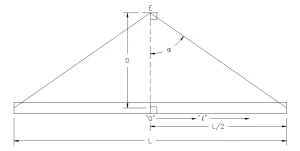
In lieu of any direct sphere measurement, for years UV lamps were measured at a standardized distance (D) of 1 meter(2) (fig. 1).
What was needed was a means of approximating the readings from an integrating sphere by a simple irradiance measurement.
The Keitz equation and the experiment
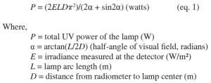
Based on the work of Keitz (3) the equation (4) bearing his name is the most widely accepted method of estimating the total UV power from a linear source. Taking a measurement per fig. 1, then:
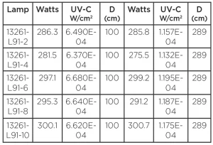
Within the records of Light Sources, Inc., the author found the results of an experiment conducted in 2013 (5). The lamps used were higher power (~300 W) amalgam lamps of arc length L=148 cm. The lamps were run under controlled input power with adequate warm up time and precautions for controlling stray surface reflectance. Irradiance measurements were made at distances of D=1 meter and D=2.89 meters. The detector used was an assembly consisting of an International Light SED240 solar blind detector, two NS254 filters and a type “W” cosine correcting diffuser. The data is shown in Table 1.
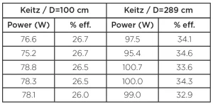
The total UV power for each reading was calculated using (eq. 1). The results are listed in Table 2.
The experiment clearly shows the inconsistency of the results for “short” measurement distances as compared to the “long” distances. In fact, the short distance results must be increased by ~27% to match the long distance. This is a very large difference which requires explanation. The first possible cause could be that the detector does not have the entire lamp in its field of view. This is a reasonable concern. At a distance of one meter for a lamp of 1.48-meter arc length, one calculates = 36.5° (0.637 radians). The full field of view must be at least twice that, 73.0° (1.274 radians).
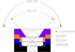
The author disassembled another detector and carefully measured all the individual components. Using AutoCAD® software, full scale drawings of each component were made then assembled into the detector. Using simple ray tracing on the drawing (fig. 2) one gets a full field of view of ~90.4° from sensor through diffuser (neglecting diffraction). If one wishes to say that any light hitting the diffuser itself will be detected by the sensor, then the angle is greater, ~167°. The author does not see this as the source for the discrepancy.
A second reasonable concern is that the sensor does not have a good cosine correction. This particular sensor does not have an individual scan of its response, and the author does not have the means of producing one. Therefore, one must depend on the information from the manufacturer (9) and on the results of others who have made such measurements on similar sensors (6)(7)(8). The author concludes that the detector would only have a few percent error from true cosine response. This is still not enough to account for the discrepancy.
Back to the origin
Going back to the original source (3) to study and understand the derivation of (eq. 1) provided several insights. Keitz dealt with visible light sources, but his methodology applies to radiation sources in general. This is not a problem. Nowhere in the book is (eq. 1) derived. Also, nowhere in the book is the suggestion made that one could determine the power of a linear radiation source from one irradiance measurement. On the contrary, Keitz was always interested in predicting the irradiance at various points and assumed that the power was already known. The method he accepted for determining total power was with an integrating sphere.
A problem that he did want to address was this: how much of an error would be expected in predicting an irradiance at some point if (a) a linear light source was treated as if it were a point source and (b) using just the inverse square law in the calculations. That lead him to what he called the “exact formula.” For the prediction of irradiance for Figure 1, the formula (Keitz, p.141, eq. (IX-19)) is (10)
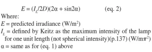
Keitz went on to compare his exact formula with the inverse square law, concluding (p.142, figure 76) that the inverse square law will give acceptable results (within 4%) when the measurement distance is greater than twice the length of the source. At the end Keitz states (p.144), “The emission of light from many present-day kinds of light source approximates so closely to uniform diffuse radiation that it is worthwhile using the exact formula for short distances.” However, there is no experimental data presented that illustrates how well his exact formula predicts the irradiance at short distances.
Completing the derivation
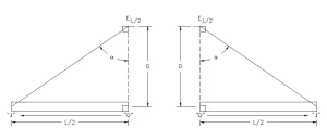
How then does one get from (eq. 2) to (eq. 1)? Equally important, why does (eq. 1) not work as intended? To answer these questions, one must look to the method of derivation as summarized in (ref. 4). One starts with the setup of Fig. 1, then simplifies it by splitting it into two identical triangles (Fig. 3). The measured irradiance (E) will be from the entire lamp. The lamp is viewed as two identical halves with two identical meters (Fig. 3).
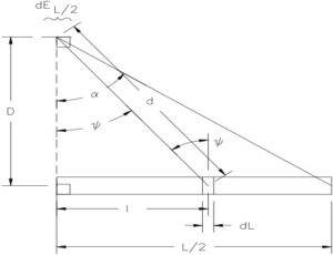
The reading of one meter is simply multiplied by two to get the entire lamp. Thus, any equation which would apply to half a lamp is doubled to get the entire lamp. The rest of the derivation comes from breaking the arc into small increments of length (dL), determining the irradiance from each small length to the detector (dEL/2), and then summing the contributions![]() .
.
Each incremental length (dL) is assumed to be a lambertian radiator whose intensity is dependent
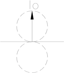
on the angle of exitance. The maximum intensity (Io) is normal to the surface element.
The lambert cosine law is applied to both the light being emitted from each increment and to the light hitting the detector. The inverse square law is applied to the intensity of the light from the varying distance (d) (fig. 4). The incremental irradiance (dEL/2) from each incremental length (dL) is:
![]()
In order to mimic the readings which would be obtained in an integrating sphere, there is a limiting distance of L < 2D (i.e. maximum arc that could theoretically fit into a sphere of radius D).
The lamp is assumed to have constant power per unit length:
![]()
This means that the incremental power (dP) from each incremental length (dL) is assumed identical and must match with (eq. 4):
![]()
This gives a means of calculating the total power if a method of determining any incremental power is determined:
![]()
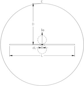
The consistency of power per unit length is important. The intensity of light is dependent on the power emitted. Hence, the intensity of light from each incremental length is also identical. At this stage the method is tied to an integrating sphere. The lamp is visualized as being in a sphere with the lamp center at the sphere center (Fig.6). The incremental length (dL) under consideration is at the sphere center.
By considering just this small increment of length at the sphere center the incremental power is related to the maximum intensity by integrating dP over the entire sphere surface. This is visually represented in (Fig 7).
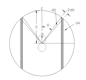
As the angle (Ø) is varied from 0 to π/2, the incremental angle (dA) sweeps out symmetrical areas (dA) on each side of the sphere. Being in the center and having this symmetry greatly simplifies the math. Half of the energy of dP emanating to the right side falls on exactly half of the sphere surface. The other half of the energy to the left falls on an identical surface area. The mathematics will not be detailed here. Suffice to say, the result is a very simple equation relating the intensity (Io) to the incremental power (dP):
Taking (eq. 7c) and substituting it into (eq. 3) gives:
![]()
Then, (eq. 6) is substituted into (eq. 8):
![]()
From (Fig. 4) the length (l) is the length of a tangent, and the distance (d) is the hypotenuse of a triangle. Both are functions of the angle (ψ). The equation for the irradiance reduces to a single variable.![]()
This can now be integrated over the angle ψ from 0 to a. This is a known definite integral function which results in the irradiance as
![]()
After re-arranging one gets the Keitz equation (eq. 1) above.
A Source of error and a possible correction
The author sees the source of the discrepancy in the use of the spherical integration and the derivation of (eq. 7c). The derivation does “integration over the surface of sphere,” but this is not identical to what occurs in a true integrating sphere. Inside a true integrating sphere, radiation is reflected a myriad of times by a “perfectly diffuse” surface. The result is the inner surface having a constant surface radiance (W/(sphere surface area-steradian)). Even if the source is not at the sphere center, the repeated reflectance creates a constant radiance. The surface radiance is size dependent (1)(11). With constant radiance one gets a constant radiant exitance (W/m2) and constant surface irradiance (also W/m2).
An irradiance meter will have a finite surface area which, when used with a sphere, will substitute for a fraction of the total sphere surface. The ratio of the meter area to the sphere surface area gives the total fraction of power it will measure. However, in the derivation above, that sphere is not a true integrating sphere. There are no repeated reflections. Without that constantly occurring diffuse reflectance the sphere radiance is not a constant. The result is (dP) being calculated as the average of all the irradiances. The sphere size component is already considered. With the radiation source being lambertian the radiance has an angular component, also considered. But, without the diffuse reflectance there is an added positional component not yet considered. This last component will affect the resulting average irradiance and, thus, the partial power calculated from it.
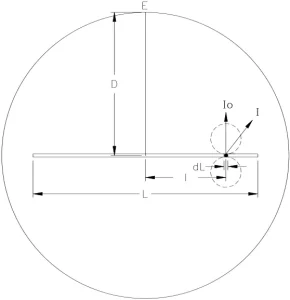
The author’s re-evaluation of the method focuses on the derivation of equations 7a to 7c. Specifically, what happens when the reference point is moved away from the lamp center? The situation then goes from that of (Fig. 7) to that of (Fig. 8):
Most importantly, the integration to find the power to intensity relationship is no longer simple or symmetric (Fig. 9).
When situated at the sphere center the intensity of light always falls perpendicular to the sphere surface. Now, that angle is 1 on one side and 2 on the other. Likewise, at sphere center the
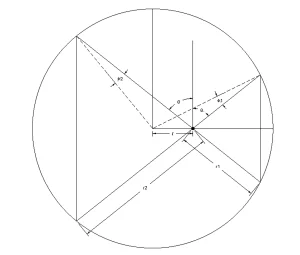
distance from the source to the sphere is always equal to D. Now, it varies as r1 and r2. The areas of the integration sphere seen by each “half” of the radiator are no longer equal. One half of the energy will be on a smaller surface while the other will be on a much larger surface. At the sphere center only one equation is needed to integrate. Now, two different integrations must be done then added together. All of this varies with the distance away from the lamp center (l).
The result of all these differences distills down to (eq. 12):
![]()
Where (dP)|l,D is the partial power calculated from an element of length (dL) at a distance (l) from the center of a sphere of radius D.
There are only two situations where this integral is easily evaluated. The first is at the sphere center where l=0. The equation becomes (eq. 7a) giving (eq. 7c). The other is when l=D. That reduces to
![]()
This presents a paradox. There is a basic assumption that the lamp has a constant power per unit length. That requires (dP) to be a constant which implies (Io) to be constant. However, (eq. 7c) and (eq. 13) indicate that something is not constant. This is the result of the non-homogenous sphere radiance described previously. The newer conversion (eq. 12) allows for variation of the sphere size (in D), the direction of irradiance from the source (in Ø) and the location away from the sphere center (in l).
There is nothing wrong with the math of (eq. 12), but one can get confused on its interpretation. In a math equation the unknown quantity is on the left side; the function on the right side should contain only known variables. With this in mind, (dP)|l,D is an unknown being calculated. It is not a constant. The only constant in the formula is (Io). The equation is showing that the power being calculated will be affected by the position of (dL). Remember, half of the energy of the incremental length is going to a smaller area of the surface. It is closer to the sphere and will have a higher irradiance but less weight in the averaging. The other half of the energy is distributed on a larger area of the sphere and at much greater distances. That gives much lower irradiance and more weight in averaging. The net result is a lower average irradiance on the sphere with a resulting lower amount of power calculated.
The author now defines the function g(l,D) as:
![]()
This can be simplified parametrically by defining the ratio

where (dP)|R is the amount of power calculated from element (dL) lying at relative position R in the sphere.
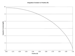
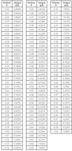
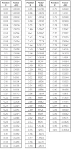
Table A and Chart A show the value of g(R) as R is varied from 0 (sphere center) to one (sphere wall) in 0.01 units. It shows how the integration varies with position along the radius of the sphere.
How does this help?
Equation 1 implies that the total power (P) is the unknown, and that the irradiance (E) being a measured quantity is known. That must be contrasted with (eq. 8), which shows that the irradiance to be measured (now an unknown) is dependent on the amount of power to be detected. That goes back further to (eq. 12) which shows that the power to be detected (unknown) will be dependent on the location of the incremental length. This is just a complex way of stating if the power measured is not what it is thought to be, the irradiance measured will be in error as will the total power calculated from it. What can be inferred from the curve of g(R) is that the further the radial distance from the sphere center (increasing R), the lower the detected power and the lower the calculated total power.
How can this relate to measurements?
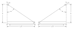
The author suggests a change in perspective of the problem. Change the thought experiment from the viewpoint of (Fig. 3) to (Fig. 10)
This is somewhat counterintuitive, but consider all the lengths, distances and angles are the same. The methodology is the same. What is different is the consideration that the measured irradiance is really referenced to the lowest value (i.e. (dP)|R) and not the highest (i.e. (dP)|R=0). From this perspective the irradiance measurements will always be too low, and the resulting calculated total power will be too low. The chart also shows that this effect is most pronounced at shorter measuring distances (where R approaches 1). At much longer distances (where R approaches 0) the variation is much smaller. This matches observations and maintains Keitz’s statement concerning treating a linear source as if it were a point source: it only works well at long measuring distances.
What is needed is a correction factor from the lowest value to that of the maximum. The maximum value of g(R) is at R=0, the sphere center. The author now takes this element as the reference position. If obtained it would give the maximum calculated power. This is now defined as the correct value for (dP) of (eq. 6), or,
![]()
And substituting (eq. 18) gives
![]()
The variable J(R) represents the correction factor needed to go from the power one calculates with (eq. 1) to the actual power.
The corrected formula
The corrected total UV power from irradiance formula becomes:
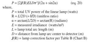
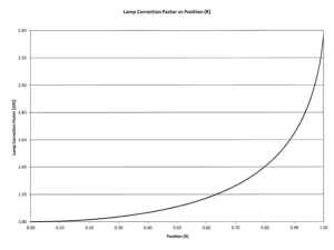
Table B and Chart B show the value of J(R) as R is varied from 0 (sphere center) to 1 (sphere wall) in 0.01 units. It shows the radial correction factor for position along the radius of the sphere.
Re-examining the experiment
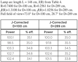
The data from Table 1 were used to calculate the total UV power using (eq. 20) with the results listed in Table 3.
The uncorrected equation results (Table 2) show no agreement of UV power with different distances D. The calculations with the corrected equation show good agreement. The power at the closer distance is equivalent to that of the greater distance which (ref. 3) indicates should be an acceptable value.
Conclusion
The corrected equation for total UV power from irradiance appears to give well correlated results for measuring a lamp at varying distances. All the requirements for obtaining good irradiance measurements (limiting reflection, proper alignment, correct distance measurements, etc.) should be met. In addition, the operator must know the usable full viewing angle of the detector to be certain that the entire arc length is being measured.
Contact: sjaworowicz@light-sources.com
References
- “Lighting Handbook: Reference and Application”, Illuminating Engineering Society of North America (1993), Figure 6-124.B, P. 322. Similar tables can be found in all past editions of the IES handbooks.
- “Tech Guide to Integrating Sphere Radiometry and Photometry”, Labsphere Inc, (https://www.labsphere.com/site/assets/files/2550/radiometry_and_photometry_tech_guide-1.pdf)
- Keitz, H.A.E. 1971. Light Calculations and Measurements. 2nd Ed., Eindhoven, Netherlands: N.V. Philips.
- Sasges, M., Robinson, J., and Daynouri, F. 2012 “Ultraviolet Light Measurement: A Concise Derivation of the Keitz Equation.” Ozone Science and Engineering 34:306-309.
- Light Sources, Inc., Engineering project 13-261 (2013). This experiment was performed by Mike Santelli and Bill Lubarsky. Dr. John Bolton was hired as a consultant and personally supervised this work.
- International Light Technologies, Typical Cosine Response Curve for the type “W” diffuser supplied by the manufacturer on request (2019).
- Sasges, M.R, A. van der Pol, A. Voronov and J.A. Robinson. 2007. Standard Method for Quantifying the Output of UV Lamps, Proc. International Congress on Ozone and Ultraviolet Technologies, Los Angeles, CA, August, International Ultraviolet Association, P.O. Box 28154, Scottsdale, AZ 85255
- Sasges, M.R. and J.A. Robinson. “Accurate Measurement of UV Lamp Output.” IUVA News 7(3):21-25 (2005)
- Michalsky, J.J., L.C. Harrison and W.E. Berkheiser III. “Cosine Response Characteristics of Radiometric and Photometric Sensors.” Atmospheric Sciences Research Center, University at Albany, State University NY Albany, Albany, NY. Document designation DOE/ER/61072—4, DE92 011437 (1992)
- For convenience and to prevent confusion, the author has converted Keitz’s variables to those used in this work. In particular his “h” is our “D”, and, his “l” is our “L”.
- Sandgren, V. “Characterization of an integrating sphere radiation reference source.” Master of Science Thesis, Department of Signals and Systems, Division of Signal Processing and Biomedical Engineering. CHALMERS UNIVERSITY OF TECHNOLOGY Göteborg, Sweden (2011). Report No. EX084/2011


