By Dan Scharpf, Ph.D., Chief Technologist, Labsphere, Inc.
Ultraviolet Germicidal Irradiation (UVGI) is a proven method of disinfection for both bacterial and viral pathogens. To ensure germicidal efficacy is achieved, UV-C light sources need accurate characterization of irradiance (optical power over a given area) and dose (irradiance x time). Knowing the limitations of the UV-C sensor can lead to better decision making when determining system performance. For accurate calibration of the sensor, it is critical to use a light source that is representative of the use-case and is also traceable to an international standard.

Calibration
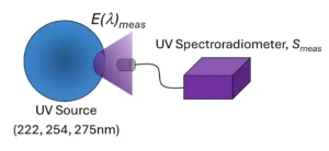
The calibration chain begins with a light source that has been measured by a National Metrology Institute (NMI) and includes an accompanying calibration certificate with an estimate of the uncertainty of the measurement. The known quantity of spectral irradiance is transferred to a high-resolution UV spectroradiometer (Image 1). The spectroradiometer then is used to measure the spectral irradiance, E(l)meas, of narrow-band sources: 222 nm, 254 nm, 265 nm or 275 nm (Image 2). These sources represent what will be seen in the field in the UVGI devices (Equation 1).

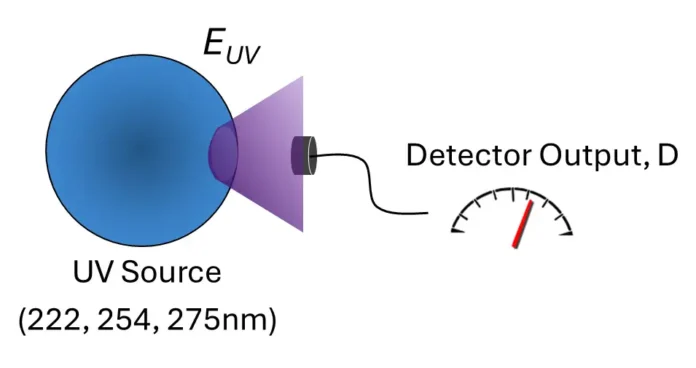
The in-band irradiance is calculated from the integral over the band of interest (Equation 2). The UV-C sensor then is substituted for the irradiance head of the spectrometer and the sensor output, D, is recorded. Since the spectral response of the sensor is not explicitly measured, the use-case is that the sensor will measure a source with a similar spectral shape to minimize spectral mismatch errors (Image 3).

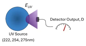
The UV-C sensor response is calculated as the ratio of the detector output, D, in amps, volts or counts, and the measured irradiance in the band, EUV (Equation 3).

Measurement Equation
The Calibration Factor, F, is the reciprocal of the response and is applied when the sensor is used in the field to measure the irradiance of a source. The measurement equation defines how the measurand is calculated (Equation 4).

Uncertainty Propagation
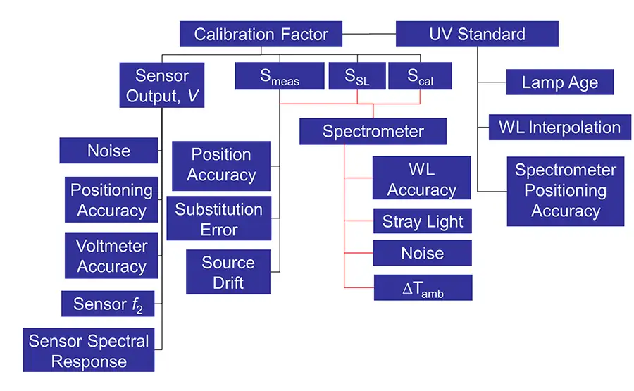
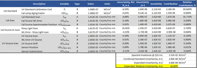
The contribution of each error source must be accounted for in the propagation of uncertainty from the individual contributors to the final measurand. Chart 1 shows all the potential contributions to the uncertainty in the calibration of the sensor.
Error Model
The contributions shown previously must now be included in the error model to evaluate the sensitivity of each term to the overall uncertainty in the measured calibration factor. Terms not explicitly included in the measurement equation are represented by a factor with a nominal value of one (1), and an associated uncertainty (Equation 5).

The uncertainty equation 1 (Equation 6) then is applied to the error model. Correlation coefficients were calculated between each source type and showed no coherence between measurements. The integration term for E(λ) however, requires the correlated term in the uncertainty analysis when the numerical integration is calculated.

Results
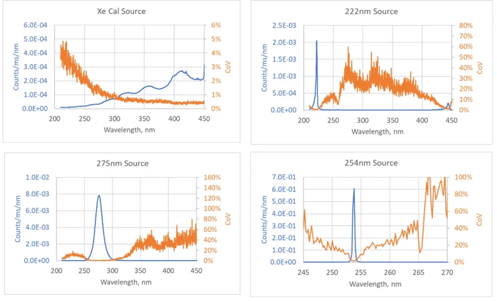
The measured noise and transience of the signal for four sources used in this process are described by the coefficient of variation which is the ratio of the standard deviation to the mean expressed as a percentage. This provides a measure of the dispersion of the measurement at each wavelength. Note that in the charts on the following page, the low signal-to-noise regions generate high CoVs since the noise is on the order of the signal. The absolute variance in these regions is actually quite low.
Since these values are outside the emission band of the sources, they contribute very little to the overall uncertainty. Chart 2 shows signal and noise levels for each source.
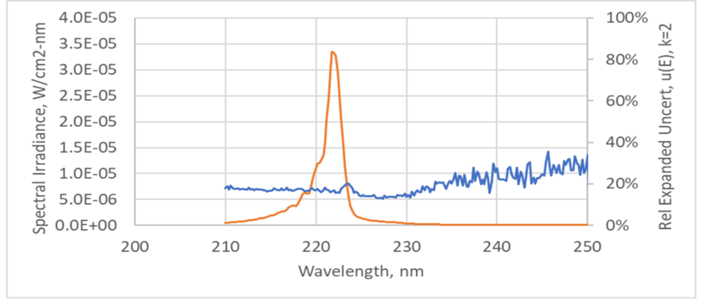
Through the uncertainty analysis, an uncertainty budget for sensor calibration can be created that shows the ranking of contributions. The UV Calibration Standard and noise from the Cal Standard spectrometer scan dominate the uncertainty. Uncertainty of integrated irradiance is lower than spectral irradiance due to summation of measurand terms (Charts 3-6). Chart 6 shows 222 nm source spectral irradiance and expanded relative uncertainty.


Purpose-built sensors for UV-C detection are calibrated against the same spectral shape as sources in the field to minimize spectral mismatch. This is critical to providing accurate measurements. It is also important to understand that the uncertainties presented reflect the uncertainty of the measured sensor response at the time of calibration. To estimate the uncertainty in the measured irradiance or dose of a UVGI device, this process must be performed again using the sensor response and uncertainty as an input to the new measurement equation.
Conclusions
- Calibration transfer method creates calibrated sensors tailored for UV sources used in field applications.
- Spectral mismatch errors can be minimized if a sensor calibration is performed using a light source that is similar to what is to be measured in the field.
- Uncertainty in sensor calibration for UV source at 254 nm can be improved with transfer from calibrated detector in lieu of spectrometer.
- Calibration standard dominates uncertainty budget. This can be improved if calibrated sources with lower uncertainty in the desired wavelengths are available.
Reference
- ANSI/NCSL Z540-2-1997 (R2007), American National Standard for Calibration – U.S. Guide to the Expression of Uncertainty in Measurement, 2007
Dan Scharpf, Ph.D., is chief technologist with Labsphere, Inc. Dr. Scharpf has been with Labsphere for 15 years with roles spanning sales, engineering management and executive management. He has contributed to the design of standard and custom systems for Labsphere’s full range of products, including light metrology, remote sensing systems and diffuse targets, with an emphasis on measurements, radiometry and uncertainty. He holds a Bachelor’s degree in Mechanical Engineering from the University of Dayton and Master’s and Ph.D. in Aerospace Engineering from the University of Notre Dame. For more information, visit www.labsphere.com.


