Editor’s Note: IUVA has approved the protocol: Method for the Measurement of the UV Output of an Underwater Combination of a Monochromatic (254 nm) Low-Pressure UV Lamp and Quartz Sleeve. The protocol was created by the IUVA Task Force on UV Lamp Measurement Underwater, with contributing authors Lianfeng Zhang (Research Institute of Tsinghua University in Shenzhen), William A. Anderson (University of Waterloo), Ted Mao (MW Technologies), Oliver Lawal (AquiSense), Jinsong Zhang (Shenzhen Water and Environment Group) and Dong Xiong (Shenzhen Jinghong Lighting). The protocol describes a test method developed to present a consistent methodology for the determination and benchmarking of UV output from the underwater “UV combination” operated by a corresponding power supply (ballast). These tests are specifically designed to yield information on the UV efficiency of the “UV combination” in a horizontal orientation in underwater conditions, where the lamp is allowed to achieve a steady-state output with a constant water temperature.
1. Background
This method is based on a published paper (Zhang et al., 2020), which extends another published measurement method for a lamp operated in open air (Lawal et al., 2017) to the measurement of the underwater combination of a UV lamp and a quartz sleeve (abbreviated as “UV combination”). The theoretical basis for this approach is derived from that used previously (Lawal et al., 2017). The two methods are therefore complementary, one for measuring lamp power in open air and this subsequent one for quantifying emitted power for under water systems when desired.
This method has been developed to present a consistent methodology for the determination and benchmarking of UV output from the underwater “UV combination” operated by a corresponding power supply (ballast). The method can be used for testing and comparing different lamp, quartz sleeve and ballast combinations, to compare test results from different laboratories and to compare operation under different water temperatures. These tests are specifically designed to yield information on the UV efficiency of the “UV combination” in a horizontal orientation in underwater conditions, where the lamp is allowed to achieve a steady-state output with a constant water temperature.
The method is not intended for general manufacturing quality control or quality assurance testing, or as a replacement for biodosimetry for determining the dose in UV water treatment systems. The method should be conducted by someone who is a UV expert and preferably by a third-party independent contractor.
Monochromatic lamps include tubular low pressure and low pressure high output (e.g., amalgam) lamps that are typically used in water treatment applications (e.g., disinfection and AOP). The method described herein is not recommended for medium pressure, pulsed, folded, non-symmetrical or other sources (e.g., excilamps – also called excimer lamps, UV LEDs).
2. Theoretical bases
2-1. The “UV combination” and the measurement object
A lamp is set inside a quartz sleeve coaxially, and then the combination is set under water. The UV output from the quartz sleeve of the combination is what is measured. The “UV combination” is theoretically treated as a UV lamp with double quartz envelopes. At the same time, the electrical power is measured to determine the apparent efficiency of the “UV combination” in radiating UV light to the surrounding environment.
2-2. For lamps operating in open air (Lawal et al., 2017)
Based on the work of Keitz (1971), the following formula is recommended for calculating the total UV output from a UV lamp with a monochromatic (e.g., 254 nm) output operated in open air. The lamp output power Pair can be calculated from Equation 1, the Keitz formula (Keitz, 1971):
P_air=(E2π^2 DL)/(2α+sin(2α)) [1]
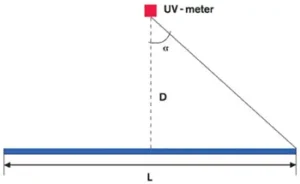
where (see Figure 1)
Pair is the UV output power of a monochromatic UV lamp operated in open air (W)
E is measured irradiance (W m-2)
D is distance (m) from lamp center to the UV sensor.
L is the lamp arc length (m) from electrode tip to electrode tip.
α is the half angle (radians) subtended by the lamp at the sensor position. That is, tan(α) = L/(2D)

Figure 1. Geometry of the measurement system (the lamp is in open air)
This expression has been tested by comparison with goniometric measurements of lamp output, and by comparing results from laboratories in different countries (Lawal et al., 2017; Sasges et al. 2007). The results are considered accurate within 5 percent and have shown good agreement between laboratories.
2-3. Underwater “UV combination”
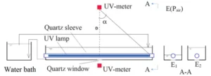
The measurement system is shown in Figure 2. Two sets of irradiance data should be taken. Firstly, the water level is set such that the quartz sleeve is partially out of the water such that there is no water in the path of the UV beams which come from the lamp and reach the UV probe position (E1 as shown in the left figure in section A-A of Figure 2). The readings of the upper and lower UV meters (E and E1) are recorded. Secondly, the water level is elevated to fully immerse the quartz sleeve, and the reading of the lower UV-meter (E2 as shown in the right figure in section A-A of Figure 2) is recorded. E2/E1 constitutes the conversion coefficient from the UV output of a lamp “in open air” to that “under water”. The UV output of the underwater “UV combination” (Punderwater) can be calculated by Equation 2 (Zhang, 2020):
P_underwater=E_2/E_1 ×P_air [2]

Figure 2. Geometry of the measurement system (the “UV combination” of UV lamp + Quartz sleeve is submerged in water)
As an option, the lower UV-meter can be replaced with a UV sensor which is set inside the water. Such sensors need laboratory confirmation that the influence from water temperature and water flow on the readings are negligible.
2-4. Efficiency of underwater “UV combination”
The output power of the “UV combination” is generally compared with the electrical power consumed (wall power) in order to calculate the efficiency of the lamp/quartz sleeve/ballast system, or compared to the electrical power delivered to the “UV combination” (lamp power) to calculate the efficiency of the “UV combination”. This is expressed by Equations 3 and 4, respectively.
Efficiency (based on wall power)(%)=100×(Total UV Output(W))/(Total Power From the Wall(W)) [3]
Efficiency (based on lamp power)(%)=100×(Total UV Output(W))/(Total Power to the Lamp(W)) [4]
3. Necessary equipment
3-1. List
(1) Radiometer or spectroradiometer
(2) Electrical equipment (power analyzer, multimeter)
(3) Thermometer
(4) Voltage regulator (automatic or manual)
(5) Water bath (temperature controller)
3-2. Calibrations or requirements of equipment
The following traceability of calibration must be confirmed, showing calibration within one year:
Radiometer with a detector must be traceable to a national laboratory (e.g. NIST, PTB, NPL, NRC, NIM etc.).
The calibration for the UV radiometer used must be valid and traceable for calibration in the UVC range, and it must include a wavelength of 254 nm. If a spectroradiometer is used, then only the output between 250 and 260 nm shall be included in the calculated output. The radiometer or spectroradiometer calibration is to be validated by a qualified third party and/or accredited facility.
Confirmation for calibration of the power analyzer. It is not sufficient to measure the ballast voltage and current to obtain the lamp power by simple multiplication, and a power analyzer must be used.
4. Necessary conditions
(1) The size of the lamp shall be in the range of 300 mm (arc length) / 15 mm (diameter) to 1500 mm / 30 mm.
(2) The water temperature shall be in the range of 5 to 30oC.
(3) To avoid a significant increase in temperature near the quartz surface the water must be flowing, especially for high power (>85 W) lamps. The necessary flow velocity is dependent on the lamp power, and should be determined through testing. Ideally, the water flow should be set to be the same as that in the intended industrial application. In the measurement system, a controller must be set to control the water temperature. To minimize operational difficulties such as condensation at cold temperatures, it is suggested that measurements are made with the water temperature set at a value similar to the room temperature.
(4) The lamp orientation shall be horizontal, see Figure 2.
(5) Reflected light effects must be avoided through use of a plate with a slit. Appendix B provides the relationships between the height of the plate and sensor, and the maximum and minimum recommended widths of the slit. If there are materials in the near vicinity of the lamp and sensor (e.g. mounting hardware such as shown in Appendix B Figure B1), the materials should have specular rather than diffuse reflectance properties as much as possible. The inside wall of the water tank should be lined with anti-reflection materials, e.g., black felt.
(6) The upper UV sensor must have an adequate cosine response for the lamp length and distance used. Cosine response means that the UV meter should have an output that is proportional to the cosine of the angle of the input beam to the normal to the UV-meter surface. This should be confirmed by measuring UV output data at different measurement distances. The measurement range should be in the range of 1/L~4L (where L represents the arc length of the UV lamp). Preparation of a figure showing the relationship of UV output vs. measurement distance is suggested, and the results should be parallel to the abscissa (x axis, L) for the distance(s) used in the method. In routine measurements, 1L is normally recommended.
5. Safety
(1) Only personnel with adequate knowledge and training in laboratory methods using UV should perform this work.
(2) Do not expose uncovered skin or eyes to UV radiation. Use adequate protective equipment, such as a UV safety shield, gloves and UV goggles. Not all plastic or glass safety glasses block UV below 300 nm. The transmission characteristics of safety glasses should be checked prior to use.
6. Measurement procedure
(Instructions to the person supervising the tests)
1) Set the voltage regulator to ensure that the electricity from the wall is regulated at the target value, appropriate to the circumstances.
2) Ensure that the quartz sleeve is clean.
3) Set the “UV combination” (the coaxial lamp and quartz sleeve) to be partially immersed in water. The water level should be set as high as possible up to the threshold of the maximum water level. This threshold value can be determined using the method outlined in Appendix C.
4) Set and control the water temperature (±1 °C tolerance), and keep water flowing.
5) Record room temperature.
6) Ignite the lamp and continuously record the reading of the lower UV meter until the readings reach a steady value. Slight random variations around the steady value are permitted.
7) Record the readings of the upper UV meter in the range L/2 to L or longer, to a maximum of 4L. For validation of the measurement system, data at several distances are suggested. For routine measurements with a validated system, a single distance test is suggested, using a distance set to be equal to the arc length (L) of the lamp being measured.
8) Record the reading of the lower UV meter.
9) Elevate the water level such that the “UV combination” is fully submerged in water. Continuously record the reading of the lower UV meter until the readings reach a steady value.
10) Record the reading of lower UV meter and the readings of electrical power for the “UV lamp” (lamp power) and/or “ballast+UV lamp” (wall power), depending on which efficiency definition is desired.
11) Calculate the UV output of the underwater “UV combination” using Equations 1 and 2.
12) Calculate the efficiencies of the “UV combination” based on lamp power and/or power from the wall, i.e., ballast+UV lamp in Equations 3 and 4.
7. Report content
The measurement report should include:
1) Description and certification of the organization and persons supervising the tests.
2) Full and detailed information about the lamp (e.g., manufacturer, identification etc.).
3) Full and detailed information about the quartz sleeve (e.g., manufacturer, identification, etc.).
4) Full and detailed information about the ballast (e.g., manufacturer, identification etc.).
5) Lamp orientation during testing (horizontal required).
6) Active arc length L (between the ends of the filaments for “linear” lamps).
7) Plot of the readings of lower UV meter vs. time after ignition.
8) Plot of the UV outputs vs. distance, at the UV steady state output.
9) Room temperature (°C).
10) Water temperature (°C).
11) Sensor and radiometer brand, model number and serial numbers for the radiometer, detector and any filters or other optical elements (e.g., diffuser) on the detector.
12) Valid, traceable radiometer or spectroradiometer calibration documentation.
13) Electrical power meter (e.g., brand, model number and serial numbers for the power meter). Confirmation of calibration or calibration certificate for the electrical power meter.
14) Measured voltage and current into the ballast.
15) “UV combination” efficiency (%) both with respect to the electrical power consumed by the “UV combination” and the “from-the-wall” electrical power.
References
Keitz. H. A. E. 1971. Light Calculations and Measurements, Macmillan and Co. Ltd., London, UK.
Lawal, O., Dussert, B., Howarth, C., Platzer, K., Sasges, M., Muller, J., Whitby, E., Stowe, R., Adam, V., Witham, D., Engel, S., Posy, P., van der Pol, A., Bolton, J. and Santelli, M. 2017. Method for the Measurement of the Output of Monochromatic (254 nm) Low-Pressure UV Lamps. IUVA News, 19(1): 9-16.
Sasges, M. R., van der Pol, A., Voronov, A. and Robinson, J.A. 2007. Standard Method for Quantifying the Output of UV lamps, Proc. International Congress on Ozone and Ultraviolet Technologies, Los Angeles, CA, August, International Ultraviolet Association, PO Box 28154, Scottsdale, AZ, 85255.
Zhang, L., Song, Y., Zhang, J., Tong, Z. 2020. Measurement of the UV Output of an Underwater Monochromatic (254 nm) Low-Pressure-Mercury UV lamp. J. Environ. Eng. 2021, 147(4): 0402006.
Song, Y., Zhang, L., Zhang, J., Zhang, Q., Tong, Z. 2020. Analysis and countermeasure of the error evoked by the reflective light from the measurement of UV irradiance. Journal of Radiation Research and Radiation Processing, 2020, 38(2): 64-72.
Appendix A: Glossary of Terms
D – distance (m) from the center of the UV lamp to the calibration plane of the UV-meter.
E – irradiance defined as the radiant power P of all wavelengths incident from all upward directions on a small element of surface containing the point under consideration divided by the area of the element. The units mW cm-2 are commonly used; 1 mW cm-2 = 10 W m-2.
L – arc length (m) of the UV lamp.
Pair – UV output from a UV lamp or a “UV combination” which is operated in open air.
Punderwater – UV output from an underwater “UV combination”.
“UV combination” – combination of a UV lamp and a quartz sleeve which is normally used in water treatment.
Appendix B: Method to Remove the Effects of Reflected UV
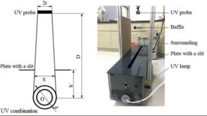
Referring to Figure B1, a plate with a slit should be set to prevent reflected light from entering the UV probe. With such a plate, all specular reflections can be removed. Therefore, it is suggested that materials with the property of specular reflection are set around the measurement system.

Figure B1 The system to measure the UV output from an underwater “UV combination” (Song et al. 2020; Supplementary Materials in Zhang et al., 2021)
If the slit width, X, is too small, some of the light beams will be interfered by the plate. If X is too large, reflections will be able to affect the UV sensor. The thresholds of maximum (X1) and minimum (X2) width of the slit can be calculated using the following formula (Song et al. 2020; Supplementary Materials in Zhang et al., 2021).
“X” _”1″ ” = d +” “h´” /”D” “(2r”-“d)” (B1)
“X” _”2″ ” = ” “h´” /”D” “(4m + 2r + d)”-“d” (B2)
Here, d is the diameter of the quartz sleeve; h’ is the height of the plate with a slit; D is the distance from the sensor to the center of the lamp; r is the radius of the UV sensor; m is the distance from the center of the lamp to the vertical wall which reflects UV light.
Appendix C: Threshold of the maximum water level
There is a maximum water level threshold that can be used for initially determining the output power in air of the partially submerged “UV combination” (Pair) as described in Section 2.2.
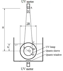
Referring to Figure C1, the vertical coordinate of Point C is the threshold of the maximum water level. It can be obtained through solving the following equations (Supplementary Materials in Zhang et al., 2021).
For Equation C1, when d/2≥r, the negative solution is selected; when d/2<r, the larger value between two solutions is selected.
 (C2)
(C2)
![]()
For Equation C4, the positive solution is selected, where XB, YB, X, Y are the coordinates of Points B and C; r is the radius of the sensor; R is the radius of the quartz sleeve; d is the diameter of the lamp; H is the distance between the lamp center and the sensor.
Figure C1 The system to measure the UV output from an underwater “UV combination” (Zhang et al., 2021)
To solve Equations C1-C4, an accompanied Excel file with VBA programming can be used.
Appendix D: Q/A on some key issues
Q1: The low-pressure lamps encompass various lengths, e.g., 2.5 meters. Taking into account the recommended vertical distance of 4 times the length (4L), this results in 10 meters, which is practically unattainable.
A1: The distance range of “L/2-4L” and the individual distance of “4L” represent distinct physical concepts. For a 2.5-meter lamp, measurements can be taken at any practically feasible distance between 1.25 meters (L/2) and 10 meters (4L), such as 1.25 meters, 1.5 meters, and so on.
Q2: Because of the open basin, micro-bubbles emerge when the water temperature decreases, adhering to both the sleeve and the basin walls. This occurrence contributes to an error of up to 10%.
A2: Assuming that micro-bubbles do appear on the sleeve, it is crucial to note that these same micro-bubbles would be present in both industrial installations and laboratory settings. Therefore, their presence would have no practical impact on the measurement outcome.
Q3: The properties of the UV-radiometer are not sufficiently defined (e.g. angular response, …).
A3: The protocol of IUVA of lamp measurement in open air (Lawal et al., 2017) had sufficiently defined the UV-radiometer. In this underwater measurement protocol, the pertinent section is directly copied from the IUVA protocol for lamp measurement in open air.
Q4: Safety is always a concern in an open arrangement.
A4: The issue of safety has never hindered the implementation of the IUVA protocol (Lawal et al., 2017), which has been successfully utilized worldwide. This protocol aims to extend the IUVA protocol (Lawal et al., 2017) to underwater measurement. So the safety concerns in this protocol are identical to those outlined in the IUVA protocol (Lawal et al., 2017). Further, refer to Appendix B of the protocol, where it is demonstrated that once the plate with a slit is properly installed, ensuring the safety of operators becomes a straightforward process. Only adequately trained personnel should perform work with UV devices.
Q5: Methods for the measurement of UV lamps are implemented in some national standards.
A5: In the German National Standard DIN 19294-1:2020 (German Standards Institute 2020 DIN 19294-1:2020) and the Austrian National Standard ÖNORM M 5873-1:2020 (Austrian Standards Institute (ASI) ÖNORM M 5873-1:2020) Devices for the Disinfection of Water Using Ultraviolet Radiation Part 1: Devices equipped with UV low pressure lamps – Requirements and testing (abbreviated as DIN/ÖNORM) two methods for the characterisation of UV-lamps are implemented. These standards are the basis for the certification of UV devices for drinking water disinfection, and should be used where required.
(1) Measurement of a UV lamp with the respective lamp control gear in an exactly defined test chamber to characterize the lamp emission in water over time and under variation of the water temperature following a standardized procedure (Schmalwieser, A. W., G. Hirschmann, J. Eggers, and R. Sommer. 2022. “A Standardized Method to Measure the Longitudinal UV Emittance of Low-Pressure-Lamps in Dependence of Water Temperature.” Water Supply 22 (1): 900-916. doi:10.2166/ws.2021.227).
(2) Characterisation of a UV lamp by means of a measurement in open air according to IUVA protocol (Lawal et al., 2017).


